SWITCHGEAR-2-15Р
With central positioning of withdrawable element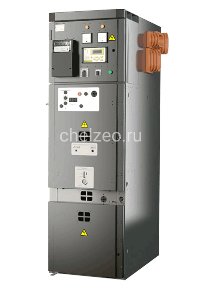
Request price on «2-15Р» or contact our manager a convenient way for you
Description
The switchgear 2-15P chambers are designed for use in three-phase electrical installations with alternating current of frequency 50 and 60 Hz at voltage 6 and 10 kV for systems with insulated or earthed neutral through an arc-suppressing coil Switchgear 2-15Ps are used both at the primary and secondary levels of power distribution. These cabinets are used by generating and grid companies, industrial enterprises, and infrastructure facilities.
The switchgear 2-15P cubicle is an assembled metal structure, the components of which are connected to each other using rivets. All metal parts of the cubicle body are made of a bent profile with a thickness of at least 2 mm. The devices and fittings of the main and auxiliary circuits are located inside the cubicle. Cubicle service conditions - one-side and two-side.
The cubicle is divided into isolated compartments to provide safety of maintenance and localization of accidents.
The cubicle consists of four compartments:
- busbar compartment;
- secondary distribution circuits compartment;
- withdrawal element compartment
- cable connection compartment
Access to the compartments from the front side is limited by doors of a special design.
Busbar compartment
The compartment houses the busbar system of the switchgear: busbars are made of high-quality copper, which is not oxidized during the entire service life of the switchgear-2-15P Busbars are made without sharp edges, with rounded edges instead in order to reduce the electric field strength. Busbars for currents up to 1600 A are made with one copper strip with a cross section of 10×80 mm, for currents up to 2500 A - two, for currents up to 3150 A - three, for current of 4000 A - three strips with a cross section of 10×100 mm. The set of fasteners, installation method and tightening moment of the bolted connections ensure the constancy of the contact pressure over the entire busbar heating range in operating and emergency modes. To localize the arc within a single Cabinet, the busbars pass through pass-through insulators mounted on a 2 mm thick steel sheet. Excess pressure resulting from an arc short circuit is discharged through a valve located at the top of the compartment.
Cable connection compartment
Cable connection compartment is used for placing, securing, and attaching cables.
This compartment contains zero-sequence current transformers, surge arresters, support insulators with a built-in capacitor, and a heating element A panel with current transformers is also installed in the compartment. The back wall of the compartment is removable and consists of two panels: upper and lower. On the front side of the compartment there is an arc-resistant door that closes with a multi-point lock. Excess pressure resulting from an arc short circuit is discharged through a valve located either at the top of the compartment or rear part of the switchgear.The compartment is designed for connecting up to four three-core cables with a core section of up to 240 mm2or twelve single-core cables with a core section of up to 630 mm2The compartment has a mechanical lock that prevents the door from being opened until the earthing device is switched on.
Withdrawable element compartment
The withdrawable element is a hardware trolley on which various equipment can be installed depending on the functional purpose of the switchgear 2-15P cabinet. The pull out element can have two positions in the compartment:
- operating position (shutter mechanism is open, contacts of the main circuit of the switch and the withdrawable element are connected, lamellar contacts enter fixed contacts at least 15 mm deep);
- control (shutter mechanism is closed, contacts of the main circuit of the switchgear and the withdrawable element are disconnected);
Secondary distribution circuits compartment
The secondary distribution circuits compartment dimensions (width 650, 800, 1000 mm; height 550 mm; depth 400 mm) allow the use of various digital devices for relay protection, control and automation, electric power monitoring and metering devices, digital converters, fiber-optic arc protection devices, terminal rows and other apparatus for secondary distribution circuits. The following devices are installed on the compartment door:
- control keys;
- signal lamps of fault and protection triggering;
- electrical measuring instrument;
- display and control units for microprocessor devices of relay protection.
Relays, terminal connections, circuit breakers, low-voltage fuses and other devices are mounted on DIN rails, which facilitates the installation and replacement of these elements. The elements of low-voltage equipment are connected to each other by stranded wires (bundles) laid in a protective box of inter-panel connections located directly on the roof of the module. Anti-condensate heating element is installed in the compartment with automatic control from the thermostat in order to protect it against impact of the environment.
The compartment is provided with LED lighting to facilitate the maintenance.
Specifications
| Parameter name | Parameter value |
| Rated voltage, kV | 6; 10 |
| Rated operating voltage, kV | 7.2; 12 |
| Rated current of main circuits of main chambers with vacuum circuit breakers, A | 630; 800; 1000; 1250; 1600; 2000; 2500; 3150; 4000 |
| Rated circuit breaking current of chambers with vacuum circuit breakers, kA | 12.5;20;25;31.5,40; |
| Thermal stability current of chamber with vacuum circuit breaker | 20; 25; 31,5,40 |
| Electrodynamic stability current of the main circuits, kA | 32; 51; 64; 80; 100 |
| Thermal stability current flow time for chambers with vacuum circuit breakers s | 3 |
| Rated current for current transformer, A | 100; 150; 200; 300; 630; 800; 1000; 2000; 3000; 4000 |
| Rated current of busbars, A | 630; 1000; 1600; 2000; 2500; 3150; 4000 |
| Rated busbar bridge current, A | 630; 1000; 1600; 2000; 2500; 3150; 4000 |
| Rated voltage of auxiliary circuits, V for: - DC and AC protection, control and alarm circuits circuits of voltage transformers (protection, measurement, accounting, AVR) circuits of transformers for private use - lighting circuits inside the switchgear | 220 ~100, ~380; 220 =12 |
| Insulation levels according to GOST 1516.3 | Normal, level “b” |
| Busbar system | With one busbar system |
| Terms of service | With one-side service/two-side service |
| Type of linear high-voltage inputs (connections) | Cable and busbar |
| Degree of protection according to GOST 14254-96 | IP20 – for exterior front sideand side walls; IP00 – for the rest of the chambers |
Advantages
Uniqueness and cost-effectiveness
- The opportunity of using Russian-made components provides an optimal price-quality ratio.
- Modular design allows for quick replacement of components, which reduces the time for preventive maintenance and repairs in emergency situations.
- The opportunity to switch off selectively in the event of an internal arc provides minimal losses in emergency situations.
Safety and reliability
- The switchgear body is divided into functional compartments by metal partitions;•Separate excess-pressure relief valves are provided for each high-voltage compartment in case of internal arc short circuits;
- Busbar compartments of adjacent cabinets are separated by metal partitions with pass-through insulators;
- The order of access to high-voltage compartments is determined by a locking system;
- Shutters block access to fixed power contacts in the control or service positions of the withdrawable element;
- Arc-resistant doors are closed with a multi-point lock;
- Visual active mnemonic clearly shows the position of the main circuit switching unit
- All operational switching of the main circuits is possible only when the doors to the high-voltage compartments are closed;
- Built-in mechanical locking system prevents incorrect actions of the service personnel;
- Capacitive voltage dividers allow to monitor the presence (absence) of voltage and perform cable phasing.
Easy operation
In the withdrawable element compartment, it is possible to perform routine work with the switch and conduct high-voltage cable tests without removing the voltage from the busbars;
The cable connection compartment is located behind a separate door Thanks to the front placement of the connection busbars and the high connection point, the most comfortable conditions for installation and maintenance of cable connections are provided;
Implementation of the possibility of maintenance and operational switching from the front side of the Cabinet.