Mobile Packaged Transformer Substations
25 ti 2500 kVA, up to 10 kV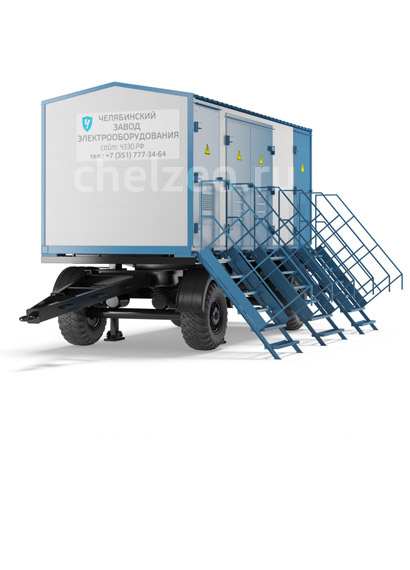
- Description
- Specifications
- Symbol
- Design classification
- MPTS structural design
- MPTS facility
- Chassis
- Example. MPTS-ShTKK-1000/10/0.4 NF1
- Photo
Request price on «Mobile» or contact our manager a convenient way for you
Description
Requirements for serviceability of high-voltage devices (HVD) and LV switchgears are set out by the substation design. The doors of switchgears of unilateral maintenance (SUM) in HVD are provided with inspection windows used for visual observation of the equipment condition without MPTS main circuits de-energization. Transformers are arranged so as to satisfy the requirements for safe observation of transformer oil level in the tank. Provisions should be made for rotating mirror installation in the power transformer compartment (on the customer’s request);its inclination angle is set in case of MPTS commissioning. In terms of mechanical strength, MPTS design ensures normal running and transportation conditions without any residual deformations or damages, which disturb normal operation of MPTS.
LV switchgear and HVD equipment withstand certain number of makes-and-breaks, which is set by relevant standards for switching devices. MPTS design ensures proper functioning of metering and accounting instruments, as well as control and alarm devices in the process of built-in devices operation.
MPTS design enables power transformer replacement without LV switchgear and/or HVDdismantling. Demountable joints of assembly units and all the MPTS bolted connections are provided with screw locking devices. MPTS are supplied fully assembled or in packages (as transport units), ready for assembling at installation site without switching devices disassembly, bolted connections reliability check and/or internal connections validity check. MPTS and single enclosures (cabinets) or transport units are equipped with lifting and movement apparatus. MPTS units lifting diagrams are shown on the facade of facility.
MPTS exterior doors hinges have an opening angle of not less than 95° and have locks and handles. Handles can be removable or combined with the key or latch. One of the MPTS outer gates wings may be complementarily closed by closing devices to avoid unauthorized entry. HV switchgear and LV switchgear door locks are secured by different combination locks and can withstand up to 1000 openings and closings. Substation exterior doors are holded in extreme positions.
Provisions are made in HV and LV switchgears of MPTS of climatic modification NF1 for air heating (by means of heating elements) to ensure installed equipment operating conditions in accordance with the requirements of respective standards and technical specifications for such equipment. Heating devices can be switched on and off either automatically or manually.
Earthing device (ED) comprising inner earth circuit is installed in the facility for electric shock hazard protection, potential equalization, and lightning-discharge protection. At least two outputs of the inner earth circuit bandwidths are provided at the facility corners to ensure the outer earth circuit connection.
Steel structures are protected against corrosion by means of base coat. Prior to steel surfaces coloring, at first it is cleared out of dirt, dust, oil, and then degreased and cleaned up to reach 2 degree according to GOST 9.402-2004.
Specifications
| Power transformer power, kVA | 25; 40; 63; 100; 160; 250; 400; 630;1000; 1250; 1600; 2000; 2500 |
| High voltage side rated voltage (HV), kV | 6; 10 |
| High-voltage (HV) side maximum operating voltage, kV | 7.2; 12 |
| Low-voltage (LV) side rated voltage, kV | 0.23; 0.4; 0.6; 0.69 |
| Main circuits AC frequency, Hz | 50±1.25 |
| Auxiliary circuits AC frequency, Hz | 50±1.25 |
| Insulation level according to GOST 1516.3: – with dry transformer – with oil transformer | Reduced Normal level "b" |
| Rated voltage of auxiliary circuits, V: – AC and DC protection, control and alarm circuits – voltage transformers circuits – lighting | 220 100 36 |
Symbol structure
Number of transformers in use (number is omitted if only one transformer is used)
Letter designation of the product: PTS is packaged transformer substation manufactured by Chelyabinsk Electric Equipment Plant LLC
Installation classification:
- M - mobile installation
Design classification:
- CH - chassis
- S - skids
Connection classification:
- Т - one-ended
Classification of lead-in on HV side:
- C - cable
- O – overhead
Classification of lead-in on LV side:
- C - cable
- O – overhead
Power transformer power, kVA
HV side voltage, kV
LV side rated voltage, kV
Climatic modification and placement category according to GOST 15150-69
Design classification
| OPTS classification attributes | Design |
|---|---|
| In terms of power transformer type | Oil, sealed oil, sealed with noncombustible liquid dielectric, dry, with cast insulation |
| In terms of method of design of transformer neutral on low voltage side (LV side) | With solid-earthed neutral; |
| With insulated neutral | With one transformer; With two transformers |
| In terms of number of power transformers in use | With one transformer; With two transformers |
| Presence of insulation in switchgear on LV side (low-voltage switchgear device) | With non-insulated buses |
| In terms of high-voltage lead-in design | Cable (C);Overhead (O) |
| In terms of design of leads using cables in LV switchgear | Cable (C);Overhead (O) |
| In terms of climatic modifications and placement category | Placement category 1, climatic modification N, NF according to GOST 15150, GOST 15543.1 |
MPTS structural design
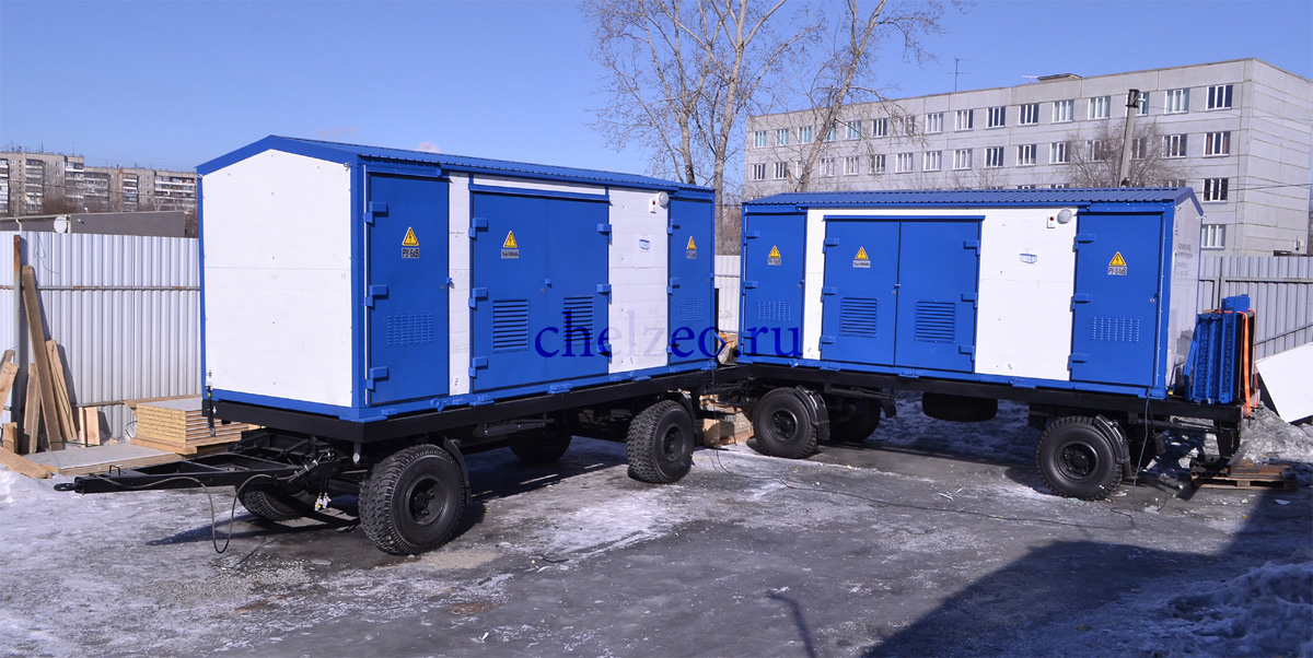
MPTS-CH consists of one facility with all the necessary equipment installed indoors, and tailor-made chassis for PTS installation.
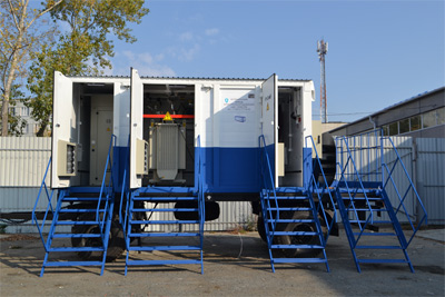
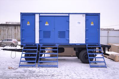
Mobile substation is composed of the following parts:
- MPTS facility;
- transportation skids or chassis;
- high-voltage device (HV switchgear);
- power transformer;
- low-voltage switchgear (LV switchgear);
- external connections device;
- auxiliary facilities
MPTS facility
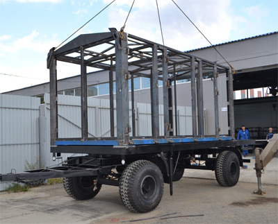
Facility represents welded metallic module. Its dimensions are determined by manufacturing plant in cooperation with the Customer on the basis of technical specifications and transportation mode.
Facility structural units ensures:
- preservation of specified thermophysical properties of the premises as per SNiP 23-02-2003;
- required technological effectiveness during production and shop assembly, transportation, installation and operation;
- minimum weight of structural unitsdue to new efficient materials utilization;
- optimal reliability and aesthetics of structural units.
PMF substructure frames are made of square tubing according to GOST 26020-83. Hot-rolled steel channels are used as frames auxiliary facilities according to GOST 8240-97. Substructures are covered with steel checkered plate of 4.0 mm thick on the top, and on the bottom - with a steel sheet of 2.0 mm thick according to GOST
19903-90. Maximum 160 mm layer thick mineral wool is placed at the base. Support frame is welded and made of closed-loop square and rectangular fabricated sections according to GOST 30245-2003. Enclosure structures are made of 3 mm thick steel plate. Sandwich panels provided with 60-100 mm thick urethane-foam and mineral wool heat insulator are used for heat insulation. The roof is covered with corrugated sheet laid on the top of the sandwich panels.
Colour scheme of modular facility shall be carried out in accordance with all the customer’s requirements. All materials employed are certified. The use of non-certified materials is not allowed.
Chassis
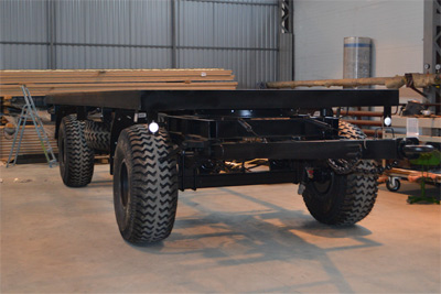
Trailer has a welded frame which consists of four frame girders interconnected by cross members. Turning device lock member located at the front of frame is designed to lock pivoting bogie in case of reverse movement. Pivoting bogie blocking and deblocking are carried out by rotating the lock member handle to one of the end positions. Lateral frame girders are provided with jacks.
Pivoting bogie is connected with the frame by a turn plate; bogie consists of a bogie frame, two sets of reinforced springs (shock absorbers), turn plate, reinforced tow bar, tow bar balancing mechanism (spring),towing eye and axle with wheels and brake chambers. The front chassis suspension consists of two spring assemblies. Middle part of the springs (reinforced shock absorbers) rests against axle support and is attached by two U-bolts. Rubber bumper is installed to limit axle stroke and mitigate impacts to the frame. The rear suspension is structurally similar to the front one. Primary braking system allows for trailer brake system connection to a tractor unit which can be equipped both with one- and two-line brake system. Parking brake system is provided with mechanical rear-wheel drive.
Trailer has reinforced towing coupler (tow bar) – with metal thickness not less than 12 mm. Conical plug used for removable towing eye gapless installation is welded at the front of tow bar. Tow bar has a spring type balancing mechanism to facilitate chassis coupling. Wheels are solid ones, with inflated tubed or tubeless tires. Trailer wheels are covered with protecting casings (wheel arch liners) along with mudguards in accordance with the requirements of Road Traffic Rules (para. 25, 7.5 and 4.7). Spare wheel is mounted on the housing bracket.
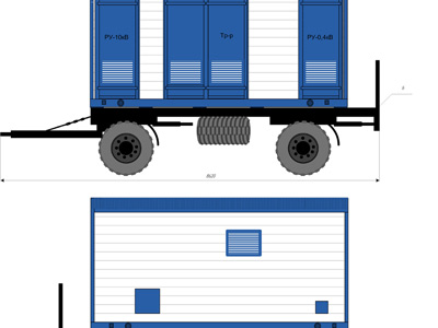
Example. MPTS-ShTKK-1000/10/0.4 NF1
Overall dimensions and layout of substation
-
Come - we will pay
Travel expenses, airfare, hotel at our expense
The promotion is valid until December 1, 2016 -
Delivery at our expense
When ordering the equipment in the amount of 5 mln. rub.
The promotion is valid until December 1, 2016 -
Electrical equipment leasing
Choose the right program
-
Come - we will pay
Travel expenses, airfare, hotel at our expense
The promotion is valid until December 1, 2016 -
Delivery at our expense
When ordering the equipment in the amount of 5 mln. rub.
The promotion is valid until December 1, 2016 -
Electrical equipment leasing
Choose the right program